| Author |
|
Handman
Senior Member

Joined: February 02 2009
Location: United States
Online Status: Offline
Posts: 229
|
| Posted: October 09 2013 at 00:52 | IP Logged
|

|
|
I am trying to find a solution to the issue of hanging PLMs needing to
be power cycled manually when they hang. I have installed an Insteon
Outletlinc and assigned it an X10 address. I have plugged the PLM into
this switched outlet and now need to add an X10 device that can be
activated by PH to cycle power to the switch when the PLM drops
offline. I am guessing I need to add a CM11A or CM17A to my pc and
then add one of these as a controller. How does PH know which
controller to use for X10?
Also, my serial port is used for the PLM; does this mean I should use
the CM17A passthrough so I don`t need another serial port? Even
though the Outletlinc is dual-band, I don't think it will pick up the RF
X10 of the CM17A, so then will a RR501 transceiver pass the wireless
X10 onto the powerline? Anyone have a better idea?
I also have an ELK M1 with an attached PLC which could transmit X10,
but I really am not sure how to make it send an X10 command from PH.
For that matter, I suppose this PLC could send an Insteon commqnd to
the Outletlinc to cycle off and on, but I don`t know how to have PH have
the Elk do this.
|
| Back to Top |


|
| |
gg102
Senior Member
Joined: January 29 2013
Location: United States
Online Status: Offline
Posts: 246
|
| Posted: October 09 2013 at 12:07 | IP Logged
|
|
|
If you intend to add a cm11a, I have a fantastic X10 solution! I fought the cm11a for many years, but now I have been using this for over a year now with NONE of the usual cm11a issues.
XTB-232
I used to have all types of issues with the cm11a freezing, sending bogus packets, not responding and power up/power down and power glitch issues. Now using Jeff's XTB-232, I have had absolutely NO issues. This device sends a stronger signal than the cm11a. Jeff also has an x10 repeater, signal tester, and other products. Jeff is a wonderful guy to work with and his products are great! I can't recommend them enough.
This XTB-232 device appears just like the cm11a to PH and works completely interchangeability, just 100% reliable unlike the cm11a.
Dave is aware of this device, and Jeff's other products.
For anyone using the cm11a, I highly recommend to get rid of it, and replace it with this device for reliable operation.
As to using it in your particular system, you can add a second controller and assign x10 devices to that controller.
|
| Back to Top |
|
| |
Handman
Senior Member
Joined: February 02 2009
Location: United States
Online Status: Offline
Posts: 229
|
| Posted: October 09 2013 at 20:29 | IP Logged
|
|
|
Thanks for the reply and the advice. I have corresponded with Jeff several times over another of his products. He is very knowledgeable and pleasant to deal with. If I was going to use this for something more involved with X10, I would get it, but this is a one-use, every few months, item. I opted to buy the CM17A since I have a V572RF32 already and I only have two serial ports and no more to spare. The CM17A is just a pass-through and cost $6, delivered. If it isn't reliable, or doesn't work, then I am only out the $6.
Anyway, thanks again for the suggestion.
Edited by Handman - December 17 2013 at 16:01
|
| Back to Top |
|
| |
dhoward
Admin Group


Joined: June 29 2001
Location: United States
Online Status: Offline
Posts: 4447
|
| Posted: October 09 2013 at 22:25 | IP Logged
|
|
|
Jeff,
Since you have a PLC connected to the Elk, I would
probably just use that to send an Insteon command to the
OutletLinc. The way you would do that is to make sure
you've loaded at least that ID into the PLC using the
M1XSP tab. Once you've got the PLC set with the Insteon
ID equated to an Elk ID (a number from 1 to 192) then you
can control it by sending the appropriate X10 command
using the Elk controller. You can do this by declaring
an X10 device type in the PowerHome Explorer and setting
the address to match the Elk ID (Elk ID 1 is A1. 2 is
A2, etc). Set this X10 device's controller to the Elk.
Then just turn this X10 device on or off to control the
outletlinc using Insteon.
The Elk only understands lighting commands in X10 format.
But the M1XSP will interpret the X10 command and send the
appropriate Insteon command using the PLC.
Hope this helps,
Dave.
|
| Back to Top |

|
| |
Handman
Senior Member
Joined: February 02 2009
Location: United States
Online Status: Offline
Posts: 229
|
| Posted: October 10 2013 at 00:00 | IP Logged
|
|
|
OK, I think I follow you, but please clarify a few points:
Do I need to load the PH and Elk IDs into the M1XSP with the null modem cable only, or do I need to hook the PLC up to my PC (and load the SDM) and load the device IDs into the PLC that way?
When I declare this new X10 devise type in PH Explorer, which boxes do I check? Should I just copy the settings for the Leviton 6280 In-Wall Receptacle?
Do I also add the OutletLinc as an X10 device and assign this newly created X10 type as the "Module Type" under the Unit menu?
Will the PLC, by way of the M1 and M1XSP then send out an Insteon command, even though I will have the macro send out an X10 command?
Edited by Handman - October 10 2013 at 14:24
|
| Back to Top |
|
| |
dhoward
Admin Group
Joined: June 29 2001
Location: United States
Online Status: Offline
Posts: 4447
|
| Posted: October 10 2013 at 13:44 | IP Logged
|
|
|
Jeff,
1. You would load the ID's using the null modem cable. What this is essentially doing is programming the M1XSP to associate X10 address (1 - 192 which equates to A1 - L16) with an Insteon address. I never really though about it before, but you may want to also program the address into the PLC since I don't think the M1XSP will actually do that. For this particular application though, it probably isnt necessary since the PLC can control an Insteon device without having its address programmed into the PLC.
2. You could use the In wall receptable as its defaults checks should be fine. If I was doing it, I would have chosen the AM466 since its the most basic X10 appliance module but if you compare the two, you'll see they're the same other than the description. Of course, you can create a new device type and copy from either of the above if you like.
3. Yes. Whether you use the new X10 Type or an existing one, you'll want to create an X10 device with a house/unit code that matches the address you assigned in the M1XSP. Set the controller to Elk.
4. Yes. Since the Elk only understands X10 commands, you send it a standard X10 lighting control command. The M1XSP will intercept this and based on its firmware, will communicate with the PLC to send an Insteon command to the appropriate Insteon address.
Dave.
|
| Back to Top |
|
| |
Handman
Senior Member
Joined: February 02 2009
Location: United States
Online Status: Offline
Posts: 229
|
| Posted: October 10 2013 at 14:06 | IP Logged
|
|
|
OK. So far so good. I even was able to connect the serial port from the ELK to the PLC and load all the device IDs (add min).
Will I see, in the PH Event Log, an outgoing Insteon Out command from the ELK controller (by way of the M1XSP and PLC) and an Insteon In response from the OutletLinc? Or will I just see the ELK send an Outgoing X10 command? If the latter, will the OutletLinc send any controller an Insteon response? I am just trying to figure out what I should be looking for during the inevitable troubleshooting.
Strange thing is I can use the PLC to send an OFF command to the OutletLinc (relay version) and it replies OFF, but the relay inside isn't clicking! Not sure what's up there. Also I used the PLC to send the X10 address, and no clicking either. Hmmmm.
Edited by Handman - October 10 2013 at 14:25
|
| Back to Top |
|
| |
dhoward
Admin Group
Joined: June 29 2001
Location: United States
Online Status: Offline
Posts: 4447
|
| Posted: October 10 2013 at 14:34 | IP Logged
|
|
|
Jeff,
In the PH eventlog, you'll only see the outgoing X10 command. If the outletlinc was a device that actually sent a command (to any linked devices as a responder) when it was manually controlled (it may...Im not sure) the Elk *might* report an incoming X10 command. If I remember correctly though, I don't think the Elk really tracked that level of incoming Insteon commands and primarily worked from the aspect of sending commands.
Concerning the relay clicking...its possible they're using an SCR rather than a mechanical relay. The real test would be to plug in a nightlite or something similar to verify if its actually controlling or not.
Dave.
|
| Back to Top |
|
| |
Handman
Senior Member
Joined: February 02 2009
Location: United States
Online Status: Offline
Posts: 229
|
| Posted: October 10 2013 at 14:58 | IP Logged
|
|
|
There's something very strange going on. I am able to send an X10 command (from the PLM plugged into the OutletLinc) to the OutletLinc and it turns off and on whether or not there is a load. When I send the Insteon command, I get the proper responses, but nothing happens at the OutletLinc, with or without a load. How is this possible? The Insteon device replies, but doesn't actually comply? Sounds like my 9 year old.
The PLM is listed as the Insteon controller of the OutletLinc in PH Explorer under the device menu, and the Elk is listed as the controller under the OutletLinc X10 device page.
And, FWIW, the "Disabled" box keeps getting checked in PH Explorer and Insteon Explorer. I am not knowing . . .
Should anything be listed as a controller of the OutletLinc? I dunno. Factory reset?
Edited by Handman - October 10 2013 at 15:03
|
| Back to Top |
|
| |
Handman
Senior Member
Joined: February 02 2009
Location: United States
Online Status: Offline
Posts: 229
|
| Posted: October 10 2013 at 15:44 | IP Logged
|
|
|
OK. I did a factory reset and removed the X10 address from the OutletLinc. I then tried to link a wall switch (switchlinc) to the Outlet and Instteon Explorer just shows FLAGGED CREATE for both devices. When I look at the device status, the "Disabled" box keeps getting checked. When I uncheck it and save, PH tries to create the link and then the box just gets checked again.
Do you think there is a defect with the OutletLinc? What could be the issue?
|
| Back to Top |
|
| |
dhoward
Admin Group
Joined: June 29 2001
Location: United States
Online Status: Offline
Posts: 4447
|
| Posted: October 10 2013 at 16:08 | IP Logged
|
|
|
Jeff,
I don't think your OutletLinc is broken. To solve the "Disabled" problem, you most likely need to set the "IEngine" field and the "Use Ext for ALDB" fields. Change both fields to a value different to what they currently are. Save your changes. Then set them to their appropriate values. Save your changes. This is a bug that was discovered with the I2CS patch. After doing this, the Disabled should go away.
Hard to say what is going on Insteon-wise without a raw log capture. Since this is a new device, I suspect it may be I2CS and must therefore have a link in its database for any device that attempts to control it via Insteon. In this case, you would want the PLM to be a controller of the outletlinc with it being a responder. In actual use, you want the PLC to control the device. In this case, easiest way to set this link up is to place the PLC in link mode by pressing its set button for 3 seconds and then pressing the set button on the OutletLinc. This should create an appropriate link with the PLC as a controller and the outletlinc as a responder. With this link in place, then the PLC via the M1XSP should be able to control it.
Dave.
|
| Back to Top |
|
| |
Handman
Senior Member
Joined: February 02 2009
Location: United States
Online Status: Offline
Posts: 229
|
| Posted: October 10 2013 at 21:38 | IP Logged
|
|
|
OK, I checked the ALBD box and I2CS, and that fixed the "flagged create" issue, but it still wouldn't respond to Insteon commands from my PLM, although it did send a response. I then tried to manually link it to the PLC and the OutletLinc went dead! During that time it had no LED and the push-button relay switch stopped responding. I had to depower the OutletLinc to get it back.
I reset it by depowering it, and then changed the IEngine to I2. I was able to link the OutletLinc to a wall switch (Icon Dimmer) and the switch operated the OutletLinc normally, however the command to turn ON or OFF the OutletLinc from the PLM produces no results (although it seems to acknowledge the commands to turn ON and OFF).
The PLM is linked as a controller of the OutletLinc.
Why is the OutletLinc not turning on/off in response to direct Insteon commands from the PLM?
Here is the raw Insteon log. The first two commands are to turn ON, then turn OFF. These were sent using the Control button on the Device Tab of Insteon Explorer. The next five lines are me turning ON the Icon Dimmer Switch (which is linked to the OutletLinc) then turning OFF the Icon Dimmer Switch.
PLM: 0F.44.B1
OutletLinc: 24:27:E6
Icon Dimmer: 15:AF:71
2013-10-10 19:13:44.171 TX &nbs p; 02 62 24 27 E6 0F 11 FF
2013-10-10 19:13:44.203 RX &nbs p; SENTINSTEON=0F 44 B1 24 27 E6 0F 11 FF 06
2013-10-10 19:13:44.500 RX &nbs p; RECEIVEINSTEONRAW=24 27 E6 0F 44 B1 2B 11 FF
2013-10-10 19:13:46.671 TX &nbs p; 02 62 24 27 E6 0F 13 00
2013-10-10 19:13:46.718 RX &nbs p; SENTINSTEON=0F 44 B1 24 27 E6 0F 13 00 06
2013-10-10 19:13:47.000 RX &nbs p; RECEIVEINSTEONRAW=24 27 E6 0F 44 B1 2B 13 FF
2013-10-10 19:13:54.953 RX &nbs p; RECEIVEINSTEONRAW=15 AF 71 00 00 01 CB 11 00
2013-10-10 19:13:56.234 RX &nbs p; RECEIVEINSTEONRAW=15 AF 71 0F 44 B1 41 11 01
2013-10-10 19:13:57.343 RX &nbs p; RECEIVEINSTEONRAW=0D 4E 66 0F 44 B1 07 19 00
2013-10-10 19:13:57.843 RX &nbs p; RECEIVEINSTEONRAW=15 AF 71 00 00 01 CB 13 00
2013-10-10 19:13:59.828 RX &nbs p; RECEIVEINSTEONRAW=15 AF 71 0F 44 B1 41 13 01
Edited by Handman - October 10 2013 at 23:16
|
| Back to Top |
|
| |
dhoward
Admin Group
Joined: June 29 2001
Location: United States
Online Status: Offline
Posts: 4447
|
| Posted: October 11 2013 at 09:02 | IP Logged
|
|
|
Jeff,
Definitely sounds strange. I decoded the raw log and the
commands to and from the PLM to the OutletLinc appear to
be fine. At first it looked as if it was an I2CS device
without the link (due to the FF on the off command) but
the flags parameter indicate an ACK (and not a NAK).
The commands from the Switchlinc though have a small
problem. First a group command is sent (this is fine)
followed by the group cleanup direct command (this is
fine as well). What we don't see is the acknowledgement
from the outletlinc to the switchlinc for the group
cleanup command. Based upon this, it would appear to me
that the OutletLinc's address is not in the PLM and you
may need to go through the whole Add Full process again.
If it was me, I would do a factory reset on the
OutletLinc. I would then delete the device entry in
PowerHome for the outletlinc. I would then put PH into
autodiscover and then press and hold the outletlinc set
button until PH recognizes it. This will create an entry
for the outletlinc and should auto detect the type.
After this entry is created, I would check the ALDB box
and set the IEngine to I2CS since its almost certainly an
I2CS device. From there, before creating any links, I
would try to control the outletlinc from the device
control. If it doesnt work, then I would create a link
from the PLM as controller and outletlinc as responder.
After that link is created, try the device control again.
Dave.
|
| Back to Top |
|
| |
Handman
Senior Member
Joined: February 02 2009
Location: United States
Online Status: Offline
Posts: 229
|
| Posted: October 11 2013 at 09:22 | IP Logged
|
|
|
Wow. Basically start from scratch. OK. I did consider that the PLM didn't get the address, or that the address sticker was wrong, so I tried autodiscovery yesterday. The result was that it was already a known device. ALso, when I did the full install I watched the device load into the PLM on the Log screen. It's easy to see because it is the last device that loads. It did only have one entry though, which seemed strange since most devices had three or four, but I dismissed it since I don't understand what all the entries mean anyway (master and slave, etc.)
FWIW, I seems to have settled into a fairly predictable pattern with loading devices fully into the PLM. It never loads until after I run the PHUPG.exe on the database first, which indicates to me that something seems to be fixed that allows the PLM to be fully loaded with links after the executable is run.
I'll go through the process you outlined and get back to you later. Thank you again for all your continuing support. You need one of those "Buy me a Beer" support buttons on the forum.
|
| Back to Top |
|
| |
Handman
Senior Member
Joined: February 02 2009
Location: United States
Online Status: Offline
Posts: 229
|
| Posted: October 11 2013 at 15:02 | IP Logged
|
|
|
OK. Mostly there. I did everything you suggested and now the OutletLinc responds to commands directly from PH. (Minor victory...yay!) I did not have to add the PLM as a Controller. So, I tried to see if the OutletLinc would respond to commands from the PLC attached to the M1XSP and Elk M1. I only saw incoming X10 received on the Elk Controller, nothing outgoing, and no response from the OutletLinc.
I then re-added all the Insteon devices to the M1XSP and even loaded all the addresses (min) to the PLC. No luck. When I connect the PLC directly to PH, I can control other Insteon lights, but not the OutletLinc. I then tried doing an "Add Full" load to the PLC instead of Add Min. Still, no change. I figured it was best to see if I could get the PLC to control the OutletLinc before just letting the Elk do it. The OutletLinc seems to be responding, but the relay isn't clicking (yes, I tried with a real load on it too).
I was unable to paste the raw log because I received an error code: An error occurred while trying to open file "" for writing. No logging will be written.
I opened PH Explorer; Setup: Controllers; PLC Controller. The Echo Log File just lists the number "5." Under the PLM controller there is a path: C:/temp/log.text. I changed the PLC log path to c:/temp/PLC_Log.txt, but it never holds. As soon as I open the controller settings again, the line is back to the number "5"!? I can rename the PLM controller path to any log file, but not the PLC's controller path file name. Presumably that is why I am getting the Echo Raw Log to File error.
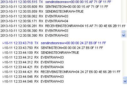
Anyway . . . I am unable to select any of the Raw Log window text, but I took a few screenshots and blended them so you can read the raw log.
The first series is a command to turn on a light (the light turns on). The second transmission is a request for the OutletLinc to turn on, but it does not. Could this be a limitation of the PLC to issue commands to IC2S devices?
|
| Back to Top |
|
| |
dhoward
Admin Group
Joined: June 29 2001
Location: United States
Online Status: Offline
Posts: 4447
|
| Posted: October 11 2013 at 15:21 | IP Logged
|
|
|
Jeff,
Sounds like you've made some progress. Concerning the
PLC, Im almost certain that the problem is related to the
OutletLinc being an I2CS device. An I2CS device cannot
be controlled by another device unless that device is
linked to the OutletLinc.
I know you had a problem before, but the best way to link
your outletlinc to the PLC will be to do it manually.
Place the PLC in link mode and then do the same to the
outletlinc. If it still doesnt work, you can create the
link using PowerHome with the outletlinc as the responder
and the PLC as the controller BUT you must do this link
creation using the PLM (the PLC is physically unable to
send the required commands to create the link in the
OutletLinc via software). So the link should create, but
it won't actually create the link in the PLC because the
PLC cant be remote programmed this way. It shouldnt
matter though since all thats really required is that the
OutletLinc have the PLC address in its database.
Hope this helps,
Dave.
|
| Back to Top |
|
| |
Handman
Senior Member
Joined: February 02 2009
Location: United States
Online Status: Offline
Posts: 229
|
| Posted: October 11 2013 at 15:54 | IP Logged
|
|
|
WHOOOOHOOOOOOO!!! I had to put that stinkin' PLC into linking mode three times, but it finally took (manual method)!  The PLC and Elk control the OutletLinc now! The PLC and Elk control the OutletLinc now!
I am overjoyed! There is no way I would have had the patience to figure this out without your persistent patience Dave.
The trigger and macro work perfecty. Now it just remains to be seen whether the whole thing will work the next time the PLM hangs. I am so relieved.
Not that I care that much now, but any idea why I got the error message for logging the raw insteon or why I can't change the log file path for the PLC (which I hope to never need except as a backup if/when the PLM finally kicks it)?
|
| Back to Top |
|
| |
dhoward
Admin Group
Joined: June 29 2001
Location: United States
Online Status: Offline
Posts: 4447
|
| Posted: October 13 2013 at 11:37 | IP Logged
|
|
|
Jeff,
Glad to hear you got it going  . .
Concerning the problems with raw log...I went back a
couple of posts and it appears that the raw log name is
probably not filled in. Open the PH Explorer, navigate
to PowerHome|Setup|Controllers and find your PLM entry.
Press the "Settings" button and enter a full path and
filename to where you'd like the log stored. Reinit and
then you should be able to check the Echo Raw log to file
option.
Hope this helps,
Dave.
|
| Back to Top |
|
| |

 Active Topics
  Memberlist
  Search
  Topic: Dedicated X10 controller


